|
How SSI can be assessed effectively for bridges? |
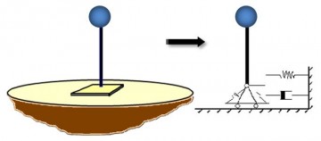
To account for SSI effect, a comprehensive 3D model needs to be created. This model should account for material and geometric nonlinearities of both the structure and the underlying soil. Since, comprehensive modeling of the structure and its supporting soil is not always practical, engineers try to account for SSI effects using discrete lumped models as shown in Figure 2; specifying the discrete lumped models parameters to properly reflect expected SSI effects.

Figure 2: consideration of a lumped parameter models (spring and dashpot) for SSI instead of a comprehensive geometric modeling
The properties for the discrete springs/dashpots in a SSI system (Figure 2) will be the result of a combined inertia and kinematic interaction mechanisms. The following four steps are commonly adopted for the calculation of SSI effect on pile supported bridge piers (Mylonakis et al. 1997):
Step 1. Site response analysis of the free field only
Step 2. Analysis of the single-pile kinematic response using free-field motions calculated in Step 1
Step 3. Computation of spring/dashpot properties at pier base using inertia interaction mechanism
Step 4. Calculation of bridge structure supported on spring/dashpot systems (Step 3) subjected to seismic motions calculated from kinematic effects (Step 2)
There several techniques for modeling either kinematic or inertia effects. However, some important features should be considered for a proper model used for engineering purposes:
• The primary load paths of the near and far field ground motions transferred to the bridge.
• Nonlinearity of soil, structure, and soil-structure interface, as well as the radiation damping of the system.
• Easy to modify in order to investigate the sensitivity of bridge performance to changes in various parameters.
The following examples show different approaches for SSI effect modeling for two common bridge typologies: Seat Type Abutment Bridges and Integral Abutment Bridges.
Seat Type Abutment Bridge
There are three approaches in order to account for pile foundations effects:
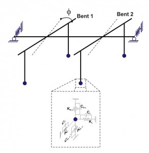
First approach: piles are replaced by some equivalent translational and rotational springs and dampers representing the whole soil underneath the bridge (Figure 3). The spring stiffness is estimated using approximate simplified methods of variable reliability. The stiffness is typically calculated by analyzing the pile foundation without any inertial contribution from the superstructure. The analysis is done usually for a single pile and the group stiffness is evaluated using pile interaction factors.

Figure 3. Translational and rotational springs and dampers representing the whole soil underneath the bridge
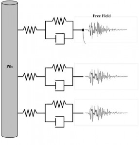
Second Approach: piles underneath the bridge are modeled, and soil around the pile at each level is simulated by a series of springs and dashpots. This approach includes two steps. In the first step, site response analysis is conducted to obtain the time history of displacement in the free-field. Then in the second step, the calculated time histories of displacement are applied to free end of soil-pile interaction elements (Figure 4).

Figure 4: Piles underneath the bridge are modeled, and soil around the pile at each level is simulated by a series of springs and dashpots
Third Approach: piles, bridge and the surrounding soil are simulated using continuum models (Figure 5). This type of modeling leads to more accurate estimation of system response; however, it is cumbersome and the computational effort can be very time consuming.

Figure 5. Continuum model for piles, bridge and the surrounding soil
[Lu, et. al (2011)]
Integral Abutment Bridges (IABs)
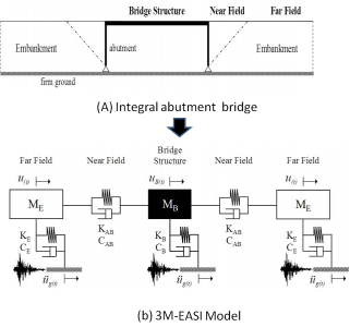
Figure 6.A represents an integral abutment bridge (IAB), the SSI effects can be effectively assessed by the 3M-EASI model (Figure 6.B), in which 3M stands for three masses and EASI stands for Embankment-Abutment-Structure Interaction.
The 3M-EASI model is a simple mass-spring-dashpot based system that takes into account the inertial and kinematic interaction of the near and the far field of the approach embankments with the bridge structure.
The far field of each approach embankment is calculated with a SDOF system using equivalent linear analysis. The near field is modeled with a spring-dashpot component and it is link between the far field and the bridge structure. Finally, the bridge structure is modeled with a SDOF system based on the fact that the mass of the bridge is concentrated in the superstructure and the axial deformation of it is negligible.

Figure 6: SSI modeling of an Integral Abutment Bridge (IAB)
References:
Lu, J., Elgamal, A., Yan, L., Law, K., and Conte, J. (2011). ”Large-Scale Numerical Modeling in Geotechnical Earthquake Engineering.” Int. J. Geomech. 11, SPECIAL ISSUE: Material and Computer Modeling, 490–503. doi: 10.1061/(ASCE)GM.1943-5622.000
